Apollo Lunar Surface Experiments Package (ALSEP) Designed to put skeptics ASLEeP?
"The ALSEP system and instruments were controlled by commands from Earth. The
stations ran from deployment until they were turned off on 30 September 1977 due
primarily to budgetary considerations. Additionally, by 1977 the power packs
could not run both the transmitter and any other instrument, and the ALSEP
control room was needed for the attempt to reactivateSkylab."
http://en.wikipedia.org/wiki/Apollo_Lunar_Surface_Experiments_Package
NONE of the
experiments have worked since 1977 except for the Laser RetroReflector,
which is suspect Experiment monitoring was shut down nine months after Jimmy Carter became
President.
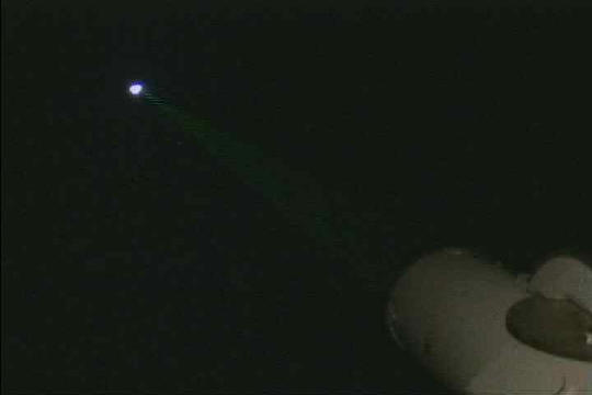
"Proof" of the lading is said to be the Lunar Laser
Reflectror, but...
Laser is reflected by the Moon anyway.
Everyone knows about how well Sun light is reflected by the Moon.
youtube.com/watch?v=bxEZXyQk4rs
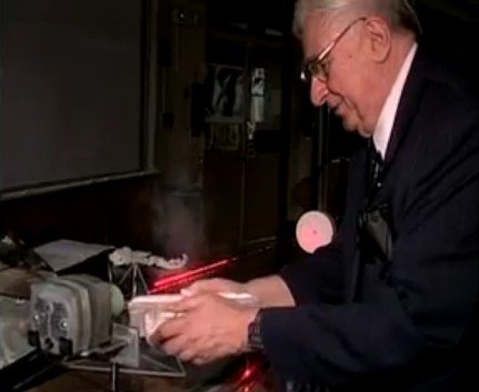
Dr. Caroll O. Alley (U Md) demonstrates laser returns
laser in parallel path
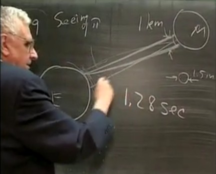
Dr. Allen shows how laser light "beam does diverge"
over many mile after 238000 miles, then disperses more on the way back, 1.28
sec. each way.
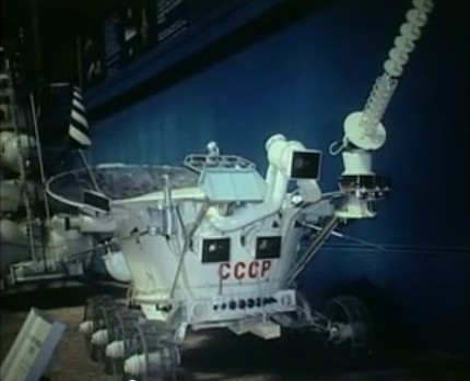
Russians have a reflector on a rover. At 238000 miles
(400000 km) there is
no way to distinguish it from Apollo's
According to the ‘debunkers,’ the fact that
observatories to this day bounce lasers off the alleged targets proves that the
Apollo missions succeeded. Some skeptics have suggested that the targets were
actually placed there robotically, but it seems unlikely that anyone would go to
so much trouble and expense when it has been known since as early as 1962 that
such targets are completely unnecessary.
In December 1966, National Geographic reported that scientists at MIT had been
achieving the same result for four years by bouncing a laser off the surface of
the Moon. The New York Times added that the Soviets had been doing the same
thing since at least 1963.
Even without the knowledge that such measurements were being accurately taken at
least seven years before the targets were allegedly placed, it would not have
been hard to figure out that there aren’t actually any laser targets on the
Moon.
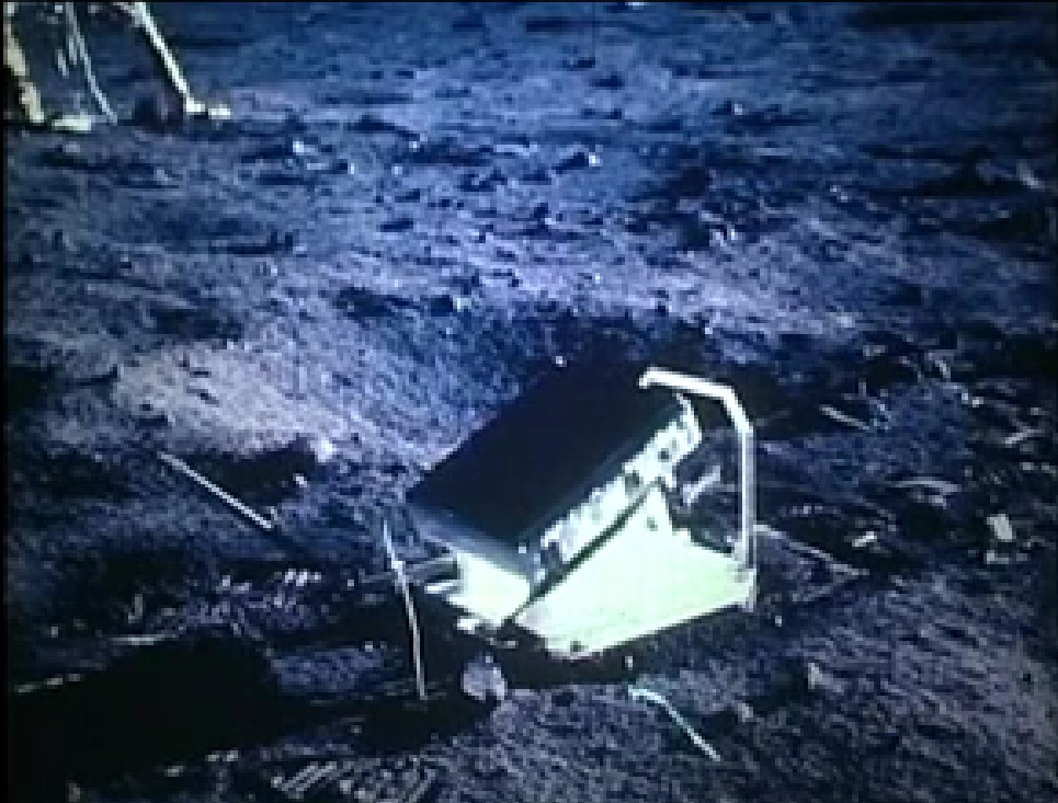
In the image above, the surrounding footprints tell us that the target is
roughly the size of the computer monitor you are now staring at. Does anyone
truly believe – and I’m including all the True Believers out there – that we had
the technology in the late 1960s and early 1970s to hit a target of that size
with a laser beam from at least 234,000 miles away? Does anyone believe that we
have the technology to do it now?
If so, then can one of NASA’s shills please explain exactly how we are able to
do it? How do we know exactly where to point the laser? How exactly do we
pinpoint the locations of the targets? The reason I ask is because the
‘debunkers’ have said for years that we don’t have anything here on Earth with
anywhere near the optical power to find the abandoned lunar modules, which is
why we have never seen any images of Earthly artifacts on the Moon. But the
laser targets are obviously much smaller than the landers, so how are we able to
‘see’ and target them?
All those probes orbiting the Moon can’t even ‘see’ the lunar modules from a
distance of only 69 miles above the lunar surface, so how exactly are we able to
pinpoint the location of something a fraction of that size from almost a quarter
of a million miles away? - Dave McGowan
Amplifier and repeater could have been
placed on the Moon
to make it appear that men landed on the Moon.
and to send back seismic data, simulate experiments set up by men.
For example, the Russians have a roving vehicle, as does China.
They can do many functions that men were supposed to have
done.
Pitifully short
horizon.
TheApollo
Lunar Surface Experiments Package(ALSEP)
comprised a set of scientific instruments placed by theastronautsat
the landing site of each of the fiveApollo
missionsto
land on the Moon followingApollo
11(Apollos12,14,15,16,
and17).
Apollo 11 left a smaller package called theEarly
Apollo Scientific Experiments Package,
orEASEP.Deployment[edit]
The ALSEP was stored in the LM's Scientific Equipment (SEQ) Bay in two separate
subpackages. The base of the first subpackage formed the Central Station while
the base of the second subpackage was part of the RTG. A subpallet was also
attached to the second subpackage which usually carried one or two of the
experiments and the antenna gimbal assembly. On Apollo 12, 13, and 14, the
second subpackage also stored the Lunar Hand Tool Carrier (HTC). The exact
deployment of experiments differed by mission. The following pictures show a
typical procedure from Apollo 12.
The
picture shows the Central Station from Apollo 16's ALSEP.
The Central Station was essentially the command center for the entire ALSEP
station. It received commands from Earth, transmitted data, and distributed
power to each experiment. Communications with Earth were achieved through a
58 cm long, 3.8 cm diameter modified axial-helical antenna mounted on top of
the Central Station and pointed towards Earth by the astronauts.
Transmitters, receivers, data processors and multiplexers were housed within
the Central Station. The Central Station was a 25 kg box with a stowed
volume of 34,800 cubic cm. In addition, on Apollos 12 to 15, a Dust Detector
was mounted on the Central Station which measured the accumulation of Lunar
dust.
Radioisotope Thermoelectric Generator (RTG)
The
picture shows the RTG from Apollo 14 with the Central Station in the
background.
The RTG was the power source for the ALSEP. It utilized the heat from the
radioactive decay ofplutonium-238andthermocouplesto
generate approximately 70wattsof
power. The base of the RTG was the base of the second ALSEP subpackage.
RTG
Cask
The RTG
cask stored the plutonium-238 fuel element. It was located to left of the
SEQ bay. The cask was designed to withstand a launch vehicle explosion in
the event of an abort or a re-entry into Earth's atmosphere (which is what
occurred on Apollo 13). The picture shows Edgar Mitchell practicing the
removal of the fuel element.
Through
the use ofseismologythe
internal structure of the Moon could be determined to several hundred feet
underground. The ASE consisted of three major components. A set of threegeophoneswas
laid out in a line by an astronaut from the Central Station to detect the
explosions.[2]A
mortar package was designed to lob a set of four explosives from varying
distances away from the ALSEP. Finally, an astronaut-activated Thumper was
used to detonate one of 22 charges to create a small shock. The diagram
shows the Thumper device.
The CPLEE
was designed to measure thefluxesof
charged particles such aselectronsandions.
Cold
Cathode Gauge Experiment (CCGE)
The CCGE
was essentially a stand-alone version of the CCIG.
Cold
Cathode Ion Gauge (CCIG)
The CCIG
experiment was designed to measure the pressure of theLunar
atmosphere. It was originally designed to be part of the SIDE, but its
strong magnetic field would have caused interference. The CCIG is on the
right of the SIDE in the diagram.
Heat
Flow Experiment (HFE)
The HFE
was designed to make thermal measurements of the Lunar subsurface in order
to determine the rate at which heat flows out of the interior. The
measurements could help determine the abundance of radioisotopes and help
understand the thermal evolution of the Moon. The HFE consisted of an
electronics box and two probes. Each probe was placed in a hole by an
astronaut that was drilled to about 2.5 m deep.
By reflecting alasershot
from Earth off one of LRRRs, the distance to the Moon could be accurately
determined. The information could be used to study Lunar recession due to
tidal dissipation and the irregular motion of the Earth. The LRRRs are the
only experiments still in use today. The above diagram shows theApollo
11version.Apollo
14's was similar to Apollo 11's. The lower diagram shows the larger
Apollo 15 version.
Lunar
Atmosphere Composition Experiment (LACE)
The LACE
was designed to detect the composition of the Lunar atmosphere.
Lunar
Ejecta and Meteorites Experiment (LEAM)
The LEAM
was designed to detect secondary particles that had been ejected by
meteorite impacts on the lunar surface and to detect primary micrometeorites
themselves.[3]SeeLunar
soilfor some experiment
results.
Lunar
Seismic Profiling Experiment (LSPE)
The LSPE
was similar to the ASE except the expected depth was to be several
kilometers. It consisted of three major components. A set of four geophones
was laid out near the ALSEP by an astronaut.[2]The
LSPE antenna was used to send signals to the charges. There were eight
charges, each consisting of various sizes ranging from 1/8 to 6 lbs. The
charges were deployed during therovertraverses.
Lunar
Surface Gravimeter (LSG)
The LSG
was designed to make very accurate measurements of lunar gravity and its
change over time. It was hoped the data could be used to prove the existence
of gravitational
waves.
Lunar
Surface Magnetometer (LSM)
The LSM
was designed to measure theLunar
magnetic field. The data could be used to determine electrical
properties of the subsurface. It was also used to study the interaction of
solar plasma and the Lunar surface.
Passive
Seismic Experiment (PSE)
The PSE
was designed to detect "moonquakes,"
either naturally or artificially created, to help study the structure of the
subsurface.
Passive
Seismic Experiment Package (PSEP)
Similar to
the PSE, except it was self-supporting. This meant it carried its own power
source (solar
arrays), electronics, and communications equipment. In addition, the
PSEP also carried a Dust Detector.
Solar
Wind Spectrometer Experiment (SWS)
The SWS
was designed to study solar wind properties and its effects on the Lunar
environment.
Suprathermal Ion Detector Experiment (SIDE)
The SIDE
was designed to measure various properties of positive ions in the Lunar
environment, provide data on the plasma interaction between solar wind and
the Moon, and to determine the electrical potential of the Lunar surface.
On Apollo 11,Buzz
Aldrinsimply carried the
EASEP to the deployment site by using handles. This is different from the
carrybar used on later missions.
Because of the risk of an early abort on the Moon, geologists persuaded NASA to
permit only experiments that could be set up or completed in 10 minutes.[4]As
a result Apollo 11 did not leave a full ALSEP package, but left a simpler
version called the Early Apollo Surface Experiments Package (EASEP). Since there
was only one 2 hour 40 minute EVA planned, the crew would not have enough time
to deploy a full ALSEP, which usually took one to two hours to deploy. Both
packages were stored in the LM's SEQ bay.
Engineers designed the EASEP to deploy with one squeeze handle, and the Laser
Ranging Retro Reflector (LRRR) also deployed within ten minutes. Despite the
simpler design, the seismometer was sensitive enough to detectNeil
Armstrong's movements during sleep.[4]
Name
Picture
Notes
LRRR
Notice
that the black dust cover has not yet been removed.
Stored on
the second subpackage as part of the subpallet.
The CCIG can be seen to the left of the SIDE. The CCIG failed after only 14
hours.
The antenna gimbal assembly was stored on the subpallet. The stool for the PSE,
the ALSEP tools, carrybar, and HTC was stored on the second subpackage.
A recording of the Apollo 13 S-IVB's impact on the lunar surface as
detected by the Apollo 12 Passive Seismic Experiment.
Because of the aborted landing, none of the experiments were deployed. However,
the Apollo 13S-IVBstage
was deliberately crashed on the Moon to provide a signal for the Apollo 12 PSE.
Name
Notes
CPLEE
Stored on
the first subpackage.
CCGE
Stored on
the first subpackage.
Only time the CCGE was flown.
HFE
Stored on
the first subpackage.
PSE
Stored on
the first subpackage.
The antenna gimbal assembly was stored on the first subpackage. The stool for
the PSE, the ALSEP tools, carrybar, and the Lunar drill was stored on the
subpallet. The HTC was stored on the second subpackage.
The above
image shows the mortar device. The lower one shows Lunar Module PilotEdgar
Mitchelloperating the
Thumper.
The mortar, geophones, and Thumper was stored on the first subpackage.
Thirteen of the twenty-two Thumper charges were fired successfully.[2]Because
of concerns about the deployment of the mortar, none of the four explosives
were fired. There was an attempt to fire them at the end of the ALSEP's
operational lifetime, but the charges failed to work after being dormant for
so long.
CPLEE
Stored on
the first subpackage.
LRRR
Stored in
Quad I of the LM and brought to the ALSEP site separately.
PSE
Stored on
the first subpackage.
SIDE/CCIG
Stored on
the subpallet.
The SIDE is in the upper-left corner while the CCIG is in the center of the
picture.
The antenna gimbal assembly was stored on the subpallet. The stool for the PSE,
the ALSEP tools, carrybar, and HTC was stored on the second subpackage.
The center
of the picture shows the electronics box and the two wires going to each of
the probes.
Stored on the second subpackage.
During the drilling operations for each of the holes, more resistance was
encountered than expected. As a result, the probes could not be inserted to
their planned depth. Accurate scientific data could not be obtained from the
Apollo 15 experiment until the data could be compared to Apollo 17's.
LRRR
Stored in
Quad III of the LM and brought to the ALSEP site via the Lunar rover.
LSM
Stored on
the first subpackage.
PSE
Stored on
the first subpackage.
SWS
Stored on
the first subpackage.
SIDE/CCIG
The SIDE
is on the left while the CCIG is attached on the right.
Stored on the subpallet.
Note the tilt of the SIDE. This was necessary because of the latitude of
Apollo 15's landing site. Also note the boom connecting the SIDE and CCIG.
This redesign was done because earlier crews complained about the difficulty
to deploy the SIDE/CCIG when only wires connected the two experiments.
The antenna gimbal assembly was stored on the subpallet. The ALSEP tools,
carrybar, and stool for the PSE was stored on the second subpackage.
The
pictures show the mortar pack (top) and thumper (bottom). Note the new
mortar base used to improve the experiment after problems were encountered
with Apollo 14's.
The mortar, geophones, and Thumper was stored on the first subpackage. The
base of the mortar box was stored on the second subpackage.
After three of the explosives were fired successfully, the pitch sensor went
off scale. It was then decided not to fire the fourth explosive. Nineteen of
the Thumper charges were successfully fired.[2]
HFE
The
picture shows the one heat flow probe that was successfully deployed.
Stored on the second subpackage.
After successfully deploying one of the probes, CommanderJohn
Younginadvertently caught
his foot on the cable to the experiment from the Central Station. The cable
was pulled out of its connector on the Central Station. Although some
technicians and astronauts on Earth believed that a repair was feasible,
mission control ultimately decided that the time necessary for a repair
could be put to better use on other work, and so the experiment was
terminated.
The ALSEP system and instruments were controlled by commands from Earth. The
stations ran from deployment until they were turned off on 30 September 1977 due
primarily to budgetary considerations. Additionally, by 1977 the power packs
could not run both the transmitter and any other instrument, and the ALSEP
control room was needed for the attempt to reactivateSkylab.
ALSEP systems are visible in several images taken by theLunar
Reconnaissance Orbiterduring its
orbits over Apollo landing sites.
LROphoto showing the
Apollo 17 ALSEP (science package)